Using PIO for LED Blinking on Raspberry Pi Pico
If we start explaining every instruction and internal detail right away, this quickly turns into documentation rather than a book. The RP2040 datasheet already does that job well. So instead, let us get straight into action.
In this exercise, we are going to do our good old LED blinking example, but this time using PIO to blink the LED. We will write a small PIO assembly program, get it running, and then explain only the instructions we actually use. This way, we build understanding step by step, rather than dumping the entire instruction set upfront, even though there are only 9 instructions.
Pio Program
We start with a minimal PIO program that runs in an infinite loop. The program configures the pin as an output and then toggles the pin between HIGH and LOW.
#![allow(unused)]
fn main() {
set pindirs, 1
loop:
    set pins, 1
    set pins, 0
    jmp loop
}
The first instruction, set pindirs, 1, configures the selected pin as an output. Using zero would configure the pin as an input. Since we are driving an LED, we set the pin direction to output (value 1).
Next, we define a label called loop:. This is not an instruction. It is just a marker that points to a location in the program. You can jump back to this location using jmp loop. You can name the label anything you want, as long as it follows the usual naming rules.
The set pins, VALUE instruction writes a value to the pins controlled by the state machine. For a single configured pin, a value of 1 drives the pin HIGH and a value of 0 drives it LOW.
RP2040/RP2350 PIO Simulator
There is a nice RP2040 and RP2350 PIO simulator that we can use to visualize and understand PIO behavior. You can paste the assembly code into the simulator, click “Assemble & Reset”, and then click “Run”. The simulator animates each instruction as it executes and shows the output level of the GPIO pins over time. Do not worry about the other options for now.
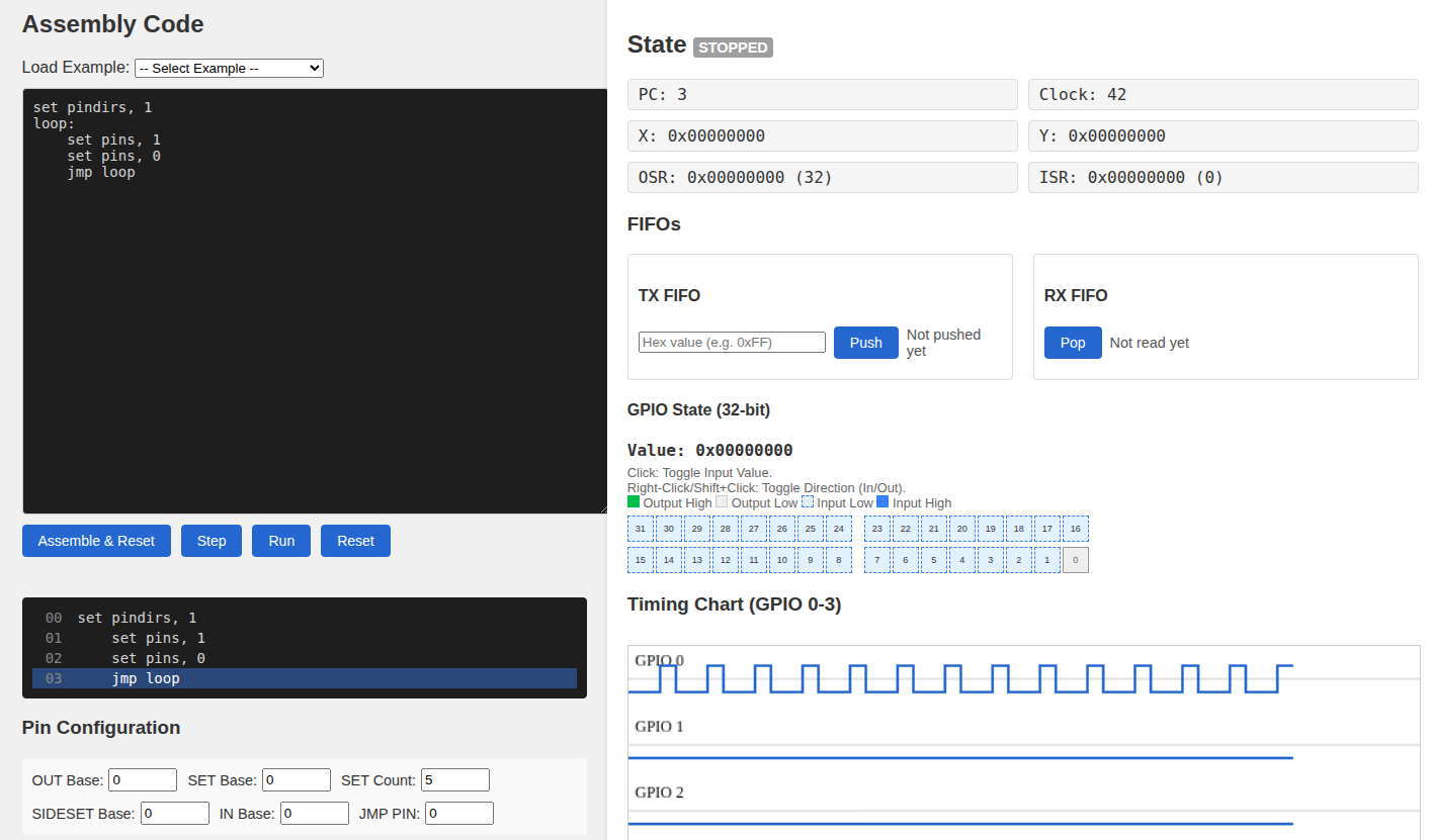
If you look at the output signal in the diagram, you may notice that the HIGH and LOW durations are not equal. The signal stays LOW longer than it stays HIGH.
Each PIO instruction takes one clock cycle to execute. For a moment, let us forget about the clock divider, or assume it is set to 1, and assume one clock cycle takes 8 nanoseconds.
The instruction set pins, 1 takes one cycle, so the signal stays HIGH for 8 nanoseconds. The instruction set pins, 0 also takes one cycle, so you might expect the signal to stay LOW for the same amount of time. But the jmp loop instruction also takes one cycle. During this jump, the pin remains LOW. As a result, the LOW state lasts for two cycles, or 16 nanoseconds.
This is why the duty cycle is not 50 percent.
So how do we fix this?
Instruction delay
PIO supports an instruction delay modifier. This modifier can be applied to any instruction and specifies how many cycles to wait after the instruction executes.
The syntax looks like this:
INSTRUCTION [DELAY_CYCLE_COUNT]
For example:
#![allow(unused)]
fn main() {
set pins, 1 [1]
}
Here, the instruction itself takes one cycle, and the delay adds one more cycle. In total, the instruction takes two cycles.
Each PIO instruction is 16 bits wide, with a 5-bit field reserved for delay or side-set. When used for delay, this field can only represent values from 0 to 31, inserting that many idle state machine clock cycles after the instruction executes.
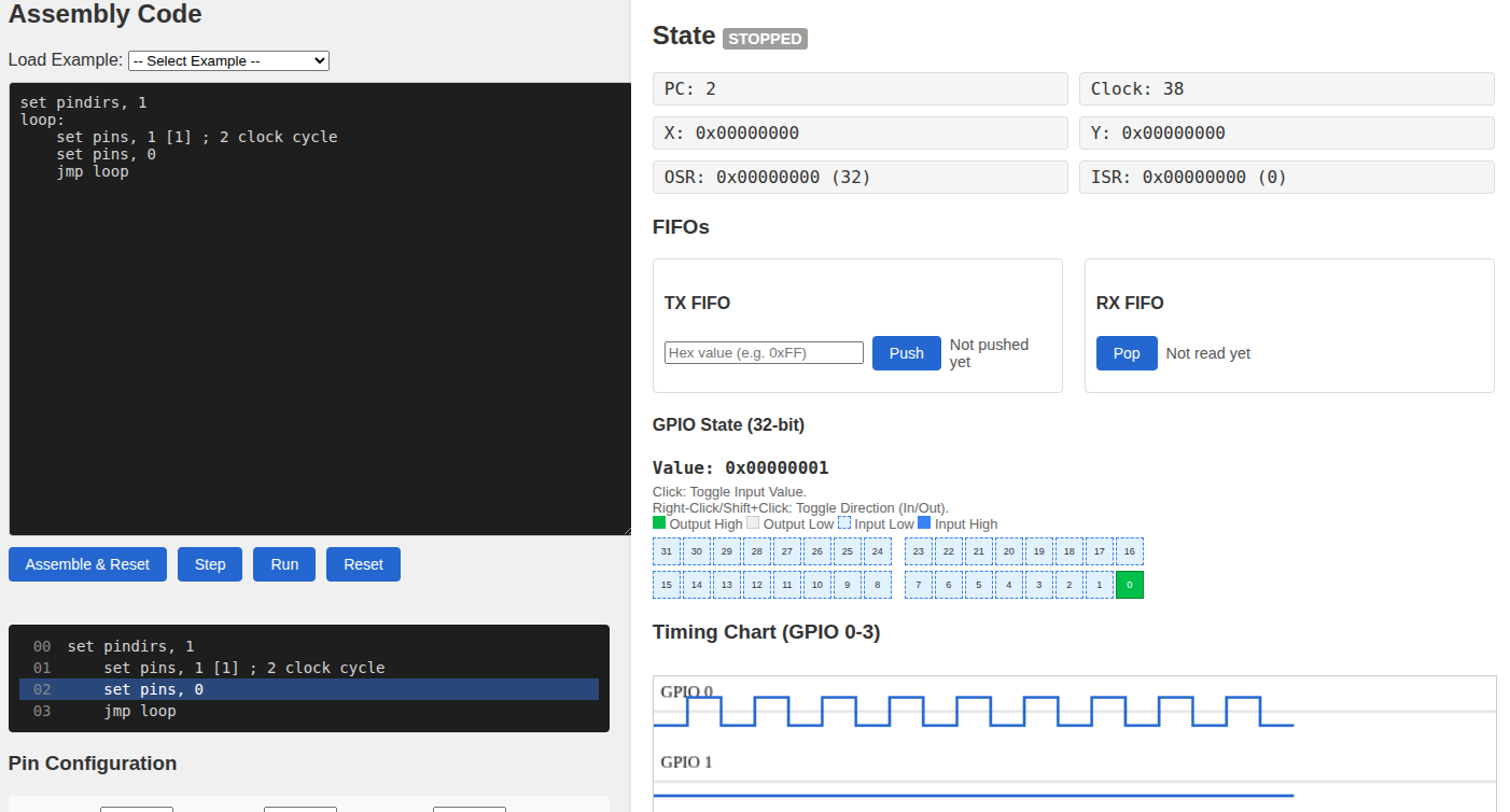
We can update our program to balance the timing.
#![allow(unused)]
fn main() {
set pindirs, 1
loop:
    set pins, 1 [1] ; 2 clock cycles
    set pins, 0
    jmp loop
}
Now the HIGH state lasts two cycles, and the LOW state also lasts two cycles. One cycle comes from set pins, 0 and one cycle comes from jmp loop. The duty cycle is now 50 percent.
No Operation
But if we try to use this program for blinking the LED, it is still far too fast to see any visible blinking effect. Setting the clock divider to its maximum value is not enough. We need more delay.
There are other ways to add delay, for example by using jump instructions. For now, we use nop because it makes the behavior easier to understand.
nop is a pseudo-instruction. It gets assembled into mov y, y. The mov instruction copies a value from a source to a destination. In this case, the Y register is copied to itself, so nothing actually changes. The instruction still takes time to execute, which makes it useful as a delay.
By combining “nop” with the delay modifier, we can make a single “nop” instruction take up to 32 clock cycles.
#![allow(unused)]
fn main() {
nop [31]
}
Final PIO Program to blink LED
From my experimentation, a single “nop” with delay is not enough to visually see the LED blinking. We need multiple “nop” instructions. When you use this program in Rust, you can experiment by reducing the number of “nop“s or adjusting the delay values and observe the effect. That is better than me explaining it further.
#![allow(unused)]
fn main() {
set pindirs, 1
loop:
    set pins, 1 [31]
    nop [31]
    nop [31]
    nop [31]
    nop [31]
    nop [31]
    nop [31]
    nop [31]
    set pins, 0 [30]
    nop [31]
    nop [31]
    nop [31]
    nop [31]
    nop [31]
    nop [31]
    nop [31]
    jmp loop
}
You should know why I used [30] instead of [31] for set pins, 0. Just in case you are wondering, it is the same reason as before. The jmp loop instruction takes one extra clock cycle while the pin is LOW. Using [30] keeps the HIGH and LOW durations equal.
We end up with 8 instructions per state, each taking 32 clock cycles, which gives 256 clock cycles for the HIGH state and 256 clock cycles for the LOW state.