Side Set
Side set is one of the most interesting features of PIO. It allows a PIO instruction to control one or more pins in the same clock cycle that the instruction executes. In the next chapter, we are going to look at the WS2812 LED where we will make use of this feature.
To use side set, we first need to tell the assembler how many side set bits we want to reserve inside each instruction. We do that with the .side_set directive:
.side_set 1
Here we reserve one extra bit in every instruction. That bit is applied to the configured side set pin in the same clock cycle that the instruction executes.
That means an instruction can do two things at once:
- Perform its normal operation
- Drive the configured side-set pin HIGH or LOW
With side_set, we can write an instruction like this:
nop side 1

; or

nop side 0
side 1 drives the configured side set pin HIGH for that instruction cycle, and side 0 drives it LOW.
Side Set with Delay
Each 16 bit PIO instruction includes a 5 bit field that is shared between delay and side set. If side set is not used, all 5 bits are available for delay, which allows a maximum delay value of 31.
Once we declare:
.side_set 1
one of those 5 bits is consumed by side set. That leaves 4 bits for delay, and the maximum delay becomes 15.
If we instead declare:
.side_set 2
two bits are used for side set. Only 3 bits remain for delay, so the maximum delay becomes 7.
Side set therefore reduces the maximum delay that can be encoded in a single instruction. This tradeoff is part of PIO program design.
Now consider:
nop side 1 [4]
The side set value is held for the entire instruction duration, including the delay cycles.
Optional Side Set
By default, once .side_set is declared, every instruction must provide a side set value.
There is another form:
.side_set 1 opt
In this mode, side set becomes optional per instruction. An extra bit is used to indicate whether the side set value should be applied. This gives more flexibility when some instructions do not need to modify the side set pin.
This also further reduces the available delay bits, since that optional flag also consumes space from the shared 5 bit field.
Why Side Set Is Useful
In many digital protocols, timing is critical. You often need to:
- Toggle a clock line while shifting data
- Generate precisely timed pulses
Without side set, you would need separate instructions to change the pin state. That increases cycle count and makes timing harder to control.
For example:
- In SPI like implementations, side set can drive the clock line while data is shifted using normal instructions.
- In a WS2812 LED driver, side set is used to precisely control the HIGH and LOW duration.
Example
Let us walk through a small example. Do not associate this with SPI or any real protocol. Just imagine a simple interface with one clock line and one data line.
The clock advances at a constant rate. The data line changes depending on what we feed into the FIFO.
You can run this directly in the PIO simulator: https://ice458.github.io/tools/pio_sim/index.html
.program sideset_demo
.side_set 1

.wrap_target

    pull           side 0        ; Load 32 bits into OSR, Clock LOW
    set x, 31      side 0        ; Bit counter = 32 bits total

bitloop:
    out pins, 1    side 0        ; Output next bit, Clock LOW
    jmp x-- bitloop side 1       ; Clock HIGH, loop until done

.wrap
In the simulator pin configuration, set the OUT base to 0 and the SIDESET base to 1. This places the data signal on GPIO 0 and the clock signal on GPIO 1.
GPIO 0 changes according to the bits being shifted out of the OSR by out pins, 1. In contrast, GPIO 1 is controlled entirely by the side-set field. Whenever you write side 0 or side 1, GPIO 1 is driven LOW or HIGH for that instruction cycle.
Both signals remain low while the state machine is stalled on the pull instruction. As soon as you push a 32 bit value into the TX FIFO, for example 0xF0A05010, the state machine begins shifting bits out.
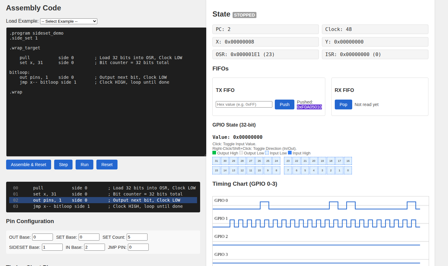
The pull instruction loads 32 bits into the OSR. The set x, 31 prepares a counter so that exactly 32 bits are transmitted. Inside the loop, out pins, 1 shifts one bit to the data pin while holding the clock low. The following jmp x-- bitloop side 1 instruction does three things at once. It drives the clock HIGH through side set, decrements the X counter, and jumps back to bitloop if the counter is not yet zero.
The important thing to observe in the timing diagram is that the clock toggles in a perfectly regular pattern, one transition per instruction, while the data line changes according to the bits being shifted out. The branching and shifting do not disturb the clock timing.
As you can see, the clock advances steadily because it is tied to instruction execution through side-set, while the data line changes as bits are shifted out. In these kinds of situations, side-set is useful because it keeps the clock timing consistent even while the program is doing other work.